loader image

Karan Tanna

The Second Hand : A Wearable for Paralysis Patients
The second hand is a tangible interaction project which aims to help enhancing the movement to grab objects for paralysed fingers. The project was done as diploma graduation project of 'How to make almost anything' taught by Prof. Neil Gershenfeld, Director of Center of Bits and Atom, MIT, USA.

This project was done during diploma course ‘How to make (almost) anything’ as graduation project, a digital prototyping diploma program taught by Neil Gershenfeld, Director at Center for Bits and Atom, MIT. This program helps to exposes to over 20 skills over 20 weeks including Web Design, Machine Design, Project Management, Electronic Design, 3D Scanning and Printing, Embedded Programming, etc. These skills are then showcased through the ‘Graduation Project’.

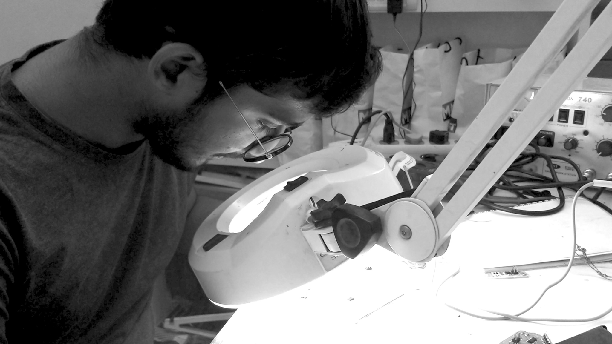
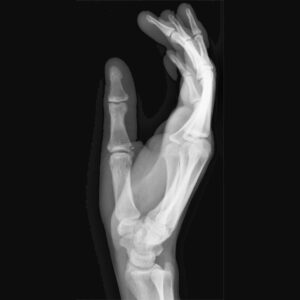
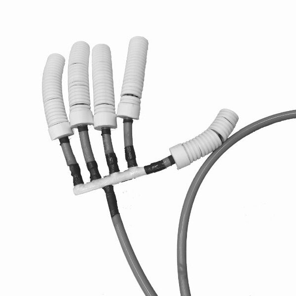
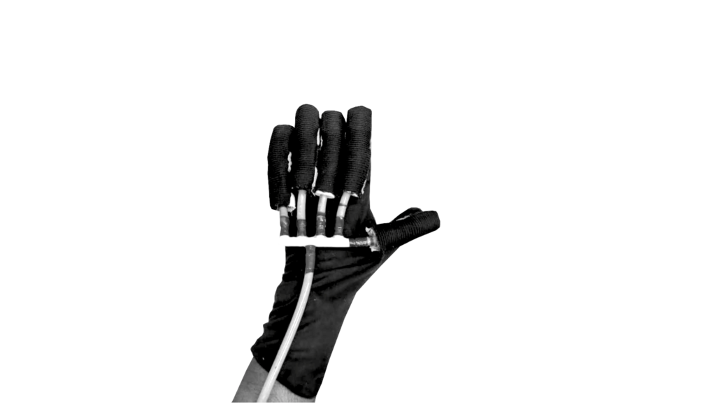
The graduation project was inspired by the problems that I faced as being differently-abled. ‘The second hand’, a wearable device; uses ‘soft robots’ and various sensors to mimic the movement of the hand and replicate it, to help in mobility to those who can’t do otherwise. It also has immense potential to become a communication device for dumb and deaf people through extension app.

Intent and Goal

People with Celebral Palsy and similar conditions have limited movement of parts, in this case fingers. However, they can move it in certain ways and in certain degrees. This can be used as potential advantage, and can be used to design a device to make their movement better.

With this project I wanted to try and build a wearable device which could assist improving locomotor functionality, in this case limited to fingers. However, this concept can be implemented and used to address other issues too.

Mechanism

The diagram shows the m I modifieechanism of the system. I modified it a bit and eliminated pressure sensor. Hence, the control box has 4 main components :

1. Air Pump, 2.  Two way Solenoid Valves, 3. Micro Controller Board & Motor Shield, 4. Connectors.

Electronics

Schematic Diagram

Schematic Diagram of Shield

To be able to run flex sensors as input. To be able to run at-least Two solenoid valves and a DC pump.To be able to run and execute program. To be able to handle FTDI and I2C connections. Also I kept in mind other aspects like clock speed and memory etc.

Board Diagram

Board Diagram of Shield

The base board above had enough for flex sensor. But this all was powered with 5V. Now my output valves and pump was rated 12V. Also Mosfets to run it. Instead of making new board and making it bigger, I wanted to keep it compact. Thus I decided to make a shield over it and power 12V seperately with DC Adapter. The I used N-gate mosfets to run each part. Thus I used 3 N-type mosfets.

Schematic Diagram of Shield

The board and shield after printing/milling and soldering 

Circuit Diagram

The diagram shows pinout/connection with sensor and ISP (In-system Programmer)

Other Components

High rated DC Motor and Solenoid Valves

Actuator Assembly of 3D printed parts and pipes

Electronic assembly

Final Assembly

Final assembly

The Glove

Hurray! Thank you for watching